

Interfacing DC Motor with PIC Microcontroller using L293D
Contents

This tutorial explains ” How to interface DC Motor with PIC Microcontroller ? “.
DC Motor and L293D
We can’t drive a DC Motor (depends) directly with a Microcontroller, as DC Motors requires high current and high voltage than a Microcontroller can handle. Microcontrollers usually operates at +5 or +3.3V supply and it I/O pin can provide only up to 25mA current. Commonly used DC Motors requires 12V supply and 300mA current, moreover interfacing DC Motors directly with Microcontrollers may affect the working of Microcontroller due to the Back EMF of the DC Motor. Thus it is clear that, it not a good idea to interface DC Motor directly with Microcontrollers.
The solution to above problems is to use H-bridge circuit.

It is a special circuit, by using the 4 switches we can control the direction of DC Motor. Depending upon our power requirements we can make our own H-bridge using Transistors/MOSFETs as switches. It is better to use ready made ICs, instead of making our own H-bridge.
L293D and L293 are two such ICs. These are dual H-bridge motor drivers, ie by using one IC we can control two DC Motors in both clock wise and counter clockwise directions. The L293D can provide bidirectional drive currents of up to 600-mA at voltages from 4.5 V to 36 V while L293 can provide up to 1A at same voltages. Both ICs are designed to drive inductive loads such as dc motors, bipolar stepping motors, relays and solenoids as well as other high-current or high-voltage loads in positive-supply applications. All inputs of these ICs are TTL compatible and output clamp diodes for inductive transient suppression are also provided internally. These diodes protect our circuit from the Back EMF of DC Motor.
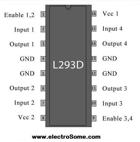
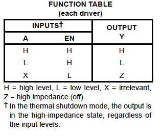
In both ICs, drivers are enabled in pairs, with drivers 1 and 2 are enabled by a high input to 1,2EN and drivers 3 and 4 are enabled by a high input to 3,4EN. When drivers are enabled, their outputs will be active and in phase with their inputs. When drivers are disabled, their outputs will be off and will be in the high-impedance state.
Interfacing with PIC Microcontroller
Circuit Diagram

Note: VDD and VSS of the pic microcontroller is not shown in the circuit diagram. VDD should be connected to +5V and VSS to GND.
We can drive two DC Motors with one L293D, in this example we are using only the first pair of drivers to drive one DC Motor. First pair of drivers are enabled by connecting EN1 to Logic HIGH. IN1 and IN2 are connected to RB0 and RB1 of PIC Microcontroller respectively which are used to provide control signal to the DC Motor. DC Motor is connected to OUT1 and OUT2 of the L293D.
MikroC Source Code
void main()
{
 TRISB = 0; // PORT B as output port
 PORTB = 1; // Set RB0 to high
 do
 {
   //To turn motor clockwise
   PORTB.F0 = 1;
   Delay_ms(2000);//2 seconds delay

   //To Stop motor
   PORTB = 0; // or PORTB = 3
   Delay_ms(2000);//2 seconds delay

   //To turn motor anticlockwise direction
   PORTB.F1 = 1;
   Delay_ms(2000);//2 seconds delay

   //To Stop motor
   PORTB = 0; // or PORTB = 3 (3 = 0b00000011)
   Delay_ms(2000); // 2 seconds delay

 }while(1);
}
Control Signals and Motor Status
| RB0/IN1 | RB2/IN2 | Motor Status |
|---|---|---|
| LOW | LOW | Stops |
| LOW | HIGH | Anti-Clockwise |
| HIGH | LOW | Clockwise |
| HIGH | HIGH | Stops |
Download Here
You can download MikroC Source Code, Proteus files etc here…


while(1) is same as while true…. means infinite loop…. always running loop
Purpose of while(1); ?
Sir will this code run on pic18f452 microcontroller? Plz reply fast..
sir, how can we check whether the L293D is working or not, easily ?
How to check L293D whether working or not ? Easily ??
How does define PORTC.F1 ??Which pin number are defined working?
Thank you.
Your pin numbers are defined working.
Hello sir, I want to use a LCD with the same design above but I can’t seem to make it work, The program was built successfully but when I uplead the hex file and run on Proteus, nothing shows up.(I used port C as output.
here is the code:
sbit LCD_RS at RB4_bit;
sbit LCD_EN at RB5_bit;
sbit LCD_D4 at RB0_bit;
sbit LCD_D5 at RB1_bit;
sbit LCD_D6 at RB2_bit;
sbit LCD_D7 at RB3_bit;
sbit LCD_RS_Direction at TRISB2_bit;
sbit LCD_EN_Direction at TRISB3_bit;
sbit LCD_D4_Direction at TRISB4_bit;
sbit LCD_D5_Direction at TRISB5_bit;
sbit LCD_D6_Direction at TRISB6_bit;
sbit LCD_D7_Direction at TRISB7_bit;
void main()
{
CMCON = 0x07; // To turn off comparators
ADCON1 = 0x06; // To turn off analog to digital converters
LCD_Init();
LCD_cmd(_LCD_CLEAR);
LCD_cmd(_LCD_CURSOR_OFF);
TRISC = 0; // PORT C as output port
PORTC = 1; // Set RC0 to high
do
{
//To turn motor clockwise
PORTC.F0 = 1;
LCD_Out(1,1,”Rotate Clockwise”);
Delay_ms(1000); // 1 seconds delay
//To Stop motor
PORTC = 0; // or PORTB = 3 (3 = 0b00000011)
Delay_ms(500); // 1/2 second delay
//To turn motor anticlockwise direction
PORTC.F1 = 1;
LCD_Out(1,1,”Rotate AntiClock”);
Delay_ms(1000); // 1 seconds delay
//To Stop motor
PORTC = 0; // or PORTB = 3 (3 = 0b00000011)
Delay_ms(500); // 1/2 seconds delay
}while(1);
}
please help!!
https://uploads.disquscdn.com/images/3920c866020fe86138ee607a75f6965bdc67bb519d899c4e16dc909cd9ac2500.png
vdd should be grouned and vss should have5v
can i use this to drive 12V, 2A Dc wiper motor along with arduino? If not can u please suggest me a IC that can work?
Dont use potentiometer for speed control use PWM instead. If still you wanna use potentiometer, add the potentiometer at the positive terminal of 12v supply (supply for motor).
https://uploads.disquscdn.com/images/1a5c600c7ec888b59f3c2c78d943e66f5d427864e3ee2d575d6f5b3ade07311a.png
may i know why my circuit is no working?
i follow the exact same code
if i want to control the motor speed using a potentiometer what should i do
Hi, any one who can share the idea on the microC code for allowing user to enter acertain numver of turns (rotation) and and after finish let the motor stop
Hello sir
I have to rotate Motar for 1° angle .
Wht cn i do?
i had downloaded the files and run the simulation in proteus with the hex file..but the motor is not spinning..why is that so?
Kindly use our forums ( https://electrosome.com/forums/ ) for asking doubts outside the scope of above article.
hello sir
can you explain what micro controller and interfacing component can I use for my project
I want to move my artificial leg for that I fix wheel in my shoe . i gng to give on button in my walking stick
I want to stop moving after 3 sec after on
what can I use ? can u explain?
Yes, ofcourse you can do it. Just decrement the pwm duty cycle with a delay in a loop.
how to coding use HI-Tech C
sir i want small help i’m doing small project 2 motors controlling with PIC controller here the problem is i want to stop motors slowly with gradual decrement in speed about 5 to 6 seconds can i stop like that is there any programm for that? plz help me sir by giving your valuble reply my mail id :[email protected] sir plz im waiting for reply
Please explain how you are expecting the motor to behave when you press a paticular button.
You are making PORTB 0 when a button is pressed.. but again setting back to 1 in the loop.
I have a doubt. I am unable to drive the motors by making use of push buttons and i need your help with that.
I am posting the code in this as well. Please guide me through.
void main()
{
TRISB = 0; // PORT B as output port
PORTB = 1; // Set RB0 to high
TRISD.F6 = 1; //Configure 1st bit of PORTD as input
TRISD.F7 = 1; //Configure 2st bit of PORTD as input
do
{
PORTB.F0 = 1;
Delay_ms(200);
if(PORTD.F6 == 0)
{
Delay_ms(200);
if(PORTD.F6 == 0)
{
PORTB = 0;
Delay_ms(200);
}
}
PORTB.F1 = 1;
Delay_ms(2000);
if(PORTD.F7 == 0)
{
Delay_ms(5);
if(PORTD.F7 == 0)
{
PORTB = 0;
Delay_ms(2000);
}
}
}while(1);
}
Sorry I don’t understand your code. Please explain in detail including how your are connecting it to microcontroller.
unable to control 2 motors simultaneously. can you tell me where exactly i am going wrong?
here’s the code:
void main()
{
TRISB=0;
PORTB=1;
while(1)
{
//To turn motor clockwise
PORTBbits.RB0 = 1;
PORTBbits.RB2 = 1;
// PORTCbits.RC5 = 0;
//PORTCbits.RC7 = 0;
delay(2000);//2 seconds delay
//To turn motor anticlockwise direction
//PORTCbits.RB0 = 0;
//PORTCbits.RB2 = 0;
PORTBbits.RB1 = 1;
PORTBbits.RB3 = 1;
delay(2000);//2 seconds delay
}
}.
Don’t you add PULL UP or PULL DOWN resistors for keypad ?
1. Try increasing the DELAY
2. For anticlockwise wise direction PORTE.F1 = 1;
3. Check the power supply, best to use separate power supply for pic and motor.
Try increasing delay.
Why you need library for DC Motor ? It is very simple to drive a dc motor. No need of any libraries.
hi, i interfacing 1293d 12v dc motor with keypad 4×4, the problem is,, when i apply 12v to the l293d.. my keypad will automatically give signal (LCD to shown password), i am using pic16f877a with mikro C.. my project about open and closed the door using keypad to log in.. can someone hep me to solve my problem… i alredy put rsistor, capacitance, but still can’t work
i have checked even with the original code the motor only turns in one direction
Greetings sir, i changed the pis where the motor is connected because i have other things connected on RTB0 and RB1 , now using RE0 and RE1 but motor only turns in one direction and does not stop. Here’s my code please help.
void main()
{
TRISE = 0; // PORT B as output port
PORTE = 1; // Set RB0 to high
while(1){
//To turn motor clockwise
PORTE.F0 = 1;
Delay_ms(2000);//2 seconds delay
//To Stop motor
PORTE = 0; // or PORTB = 3
Delay_ms(2000); //2 seconds delay
//To turn motor anticlockwise direction
PORTE.F0 = 1;
Delay_ms(2000);//2 seconds delay
//To Stop motor
PORTE = 0; // or PORTB = 3 (3 = 0b00000011)
Delay_ms(2000); // 2 seconds delay
}
}
Motor only turns in one direction, does not change. Please help.
Hi , where can i find Dcmotor library??
if(Switch Pressed)
{
PORTB = 0;
}
Hi sir ,
Hare your coding auto stop, i want stop button system. i am trying but not working…
can u help me sir…
my code:
void main()
{
TRISB = 0; // PORT B as output port
PORTB = 1; // Set RB0 to high
TRISD.F0 = 1; //Configure 1st bit of PORTD as input
TRISD.F1 = 1; //Configure 2st bit of PORTD as input
do
{
//To turn motor clockwise
PORTB.F0 = 1;
Delay_ms(200);//2 seconds delay
//To Stop motor
if(PORTD.F0 == 0) //If the switch is pressed
{
Delay_ms(5); //Switch Debounce
if(PORTD.F0 == 0)//If the switch is still pressed
{
PORTB = 0; // or PORTB = 3
Delay_ms(200);//2 seconds delay
}
}
//To turn motor anticlockwise direction
PORTB.F1 = 1;
Delay_ms(200);//2 seconds delay
//To Stop motor
if(PORTD.F1 == 0) //If the switch is pressed
{
Delay_ms(5); //Switch Debounce
if(PORTD.F1 == 0)//If the switch is still pressed
{
PORTB = 0; // or PORTB = 3 (3 = 0b00000011)
Delay_ms(200); // 2 seconds delay
}
}
}while(1);
}
It seems like your battery don’t have enough power to start the motor. Motor need high current for starting… so the voltage decreases during starting time.. But if your power supply is not capable of providing starting current… it will remain in that state.
What problem ?
Actually pls help anyone ..i have the same voltage drop problem..i used 9vnippo battery,but when i checked motor ouput terminals it came as 3.2 volt…y that much drop..is anything i have to modify
Me too have a same problem…i dnt know y it came lik that
Sorry, I don’t understand what you are asking.
It is RB0 and RB1 as indicated in the circuit diagram and program.
How are you Sir?Well ,l would like to ask whether you connect( RBO and RB2 )on the circuit diagram or you connect (RBO and RB1)?Thank you very much in advance.
How are you Mr George.Well,l’m doing a project on DC Motor control(Direction control as well as Breaking).l have set up the circuit you gave on this platform as well as using MikroC for the code.The problem is the circuit is operating on its own (going clockwise for some time stops a while and then goes anticlockwise).l would want to manually control the circuit to have it stop and run clockwise as well as anticlockwise under my command.My knowledge in C programming at the moment is not really that good ,so l would be very grateful if you assist me in manipulating the circuit to follow these commands(RB0:RB2)= (1,1) or (0,0) the motor stops,(1,0) it goes clockwise,(0,1) it goes anticlockwise.l have introduced Logic toggle on both RB0 and RB2).Thank you very much in advance.So if there is need for a new code,what is that l have to adjust??
How are you?l hope l found you well.l have set up the circuit as done above and used the code.The circuit is working as follows,it moves in clockwise direction and then stops and starts moving in an anticlockwise direction(its doing this automatically once l start to run proteus).l would like to manipulate it myself such that l have it move in a clockwise direction,stop it and also have it move in an anticlockwise direction.Please help me there,how can l go about that.l would very much appreciate your help.
You may use 4 hours delay for that…….
can this motor work in such a way that it comes ON atleats every 4hours?????
Thank for telling us the mistake.
The circuit diagram is correct, and that article is corrected.
You can use any of the following compilers.
MikroC
CCS C
MPLAB XC8 etc.
https://electrosome.com/dc-motor-speed-control-pic-pwm/
Hi,
First of all thnks for the tutorial, second I want to know how can I use this PIC and this IC to control the SPEED of the motor ??
Sorry, I don’t have its photos.
Sorry, It will be very difficult…
You will get *.hex file after compiling the c program.
Since you are using MikroC, we can the same code for 16F877A with little / no changes…
Just change the PIC in mikroC project settings..
I also recommend you to change the register that used for output values from PORT to LAT..
hello sir ,how can i change that languge to an assembly
Can i see your project?
Can you post a tutorial where we can chose the direction of rotation of a DC motor and then control it’s speed using PIC18F4550?
Yes….. you can..
following article will help you.
https://electrosome.com/getting-started-pic-18f-microcontroller/
ca i do it using pic18f4550?
Please read this tutorial : https://electrosome.com/push-button-switch-pic-microcontroller/
hii…i have a doubt about how to write a program to detect the input signal at the input port
i mean..if a input is detected in a input port then only the program should run
reply soon
Hello Sir. I am doing the project titled REMOTE CONTROLLED SURVEILLANCE ROBOT. I need your help especially on how to rotate the camera using motors. Please do provide help. My email Address is: [email protected]
Above project is tested and verified in proteus.
Thanks, i asked because I can’t simulate this one, don’t know the problem. I’ll see if I can fix it.
In this tutorial we will just rotate the dc motor in clockwise and anti-clockwise directions..
but in that one.. we are controlling the speed of dc motor using PWM.
For free technical support related to above article please comment here..
For another topics, please use our forums, http://electrosome.com/forums/
My email :
[email protected]
Hi Ligo, How can i contact you, please suggest
Hello,
Please use our forum (http://electrosome.com/forums) for free technical support.
Hi, i am working on project spy robot using pic 18f4550 and zigbee. Please guide me
What you meant by standard C ?? ANSI C ??
There are different C compilers…. like Turbo C, Broadland C etc..
MikroC, MPLAB XC8 C, CCS C, Hi-Tech C are the commonly used C compilers for PIC Microcontrollers…..
bro, what are the differences between this microC code and standard C code ? I need to know that because we are not allowed to use microC in our project
Yes, ofcourse. Try the following link.
http://electrosome.com/interfacing-relay-with-pic-microcontroller/
hi..can I change the ic with relay?
http://electrosome.com/dc-motor-speed-control-pic-pwm/
this is an assignment I have from my university design and discuss the digital system that uses the pwn of the pic 18f8722 microcontroller to control the speed of a dc motor ? kindly assist
Please elaborate your need..
i want to connect buck converter to the above ckt how i can
This is well done! I was wondering if you had ever had the problem where your motor voltage (12v) gets dropped when connected through the L293? I have set up a circuit to control a 9V DC motor with an L293. So my motor voltage is 9V, and my chip voltage is 5v. However, my motor voltage drops to about 3v and therefore doesn’t supply enough power for the motor. I’ve read where the chip can drop the voltage by 2-3 volts (which I could live with), but this drop is more like 6-7 volts. Thanks
CAN I KNOW, WHAT IS THE FUNCTION OF CRYSTAL IN THIS DIAGRAM?
can i control just one dc motor with the h-bridge?
Read our stepper motor tutorials and try designing yourself..
can someone help to build a schematic diagram??
i need to move back and forth three stepper motor in sequences.
using only one switch,i need to move the first motor 180 degree clock wise and then move anticlockwise back to its original position. as soon as the first motor stop, the second motor will repeat the process and so does the third motor..and stopped..
Yes you are right… I will work with and without that code… It is used to turn off the comparator module of PIC which uses pins RA4 and RA5……
If you are using pins RA4 or RA5 as digital I/O, then you must disable it… otherwise it is not necessary..
Hi, this is a great tutorial. Could you please tell me the purpose of this line of code: CMCON = 0x07; // To turn off comparators. I have been successful in running the motor, both with and without this line of code but I am just beginning to learn C and therefore am curious about its purpose. Thanks.
Yes, ofcourse… try connecting the pwm output to enable input of L293D..
can I connect L293d with (ccp pin) and control the motor speed by using (pwm) ?
Hello,
It is simple.. .as output of PIR sensor is digital…
Connect it to an input pin of pic..(similar to using switch http://electrosome.com/push-button-switch-pic-microcontroller/ ).. .. switch on the motor if motion is detected as above example..
i am working on a project -Automatic sliding doors, where 2 motors are used for the movement of the door. (MCU-pic16f877a) The doors open when the PIR sensor detects movement. How do i program my mcu such that the motors work when motion is detected and stop when no motion is detected?
Connect the Vss pin of L293D to 3.3V.. it is the logic voltage input of L293D….
No other changes are required..
You can connect the input pins IN3 and IN4 of L293D to PIC Microcontroller .. connect EN2 to VDD to enable second module of L293D…
Connect the second motor to OUT3 and OUT4..
I am trying to use l293 with 3.3 v controller.what changes do I are o do in the above mentioned circuit
Also does what are the limits for the enable pin? Can I directly connect it to Vcc?Or should I attach a resistor to limit the current?
How do I control two motors i.e quadruple half-H drivers using this IC ?
Could you elaborate the output of two motors according to inputs (truth table) ?
Sorry, I don’t get your question.. .Can you please elaborate..??
is there a way to send out two different signals at the same time? using this code?
thank’s man..u are a great man..
use separate power supplies for motor and pic.. with common ground… use proper filters for the power supplies…try after increasing the delay of motor rotation..
why it won’t work when i use proteus…i don’t understand how its work..can’t u explain in details pleasee..its not function at all after i enter the source code..
Hello, the about article is for controlling dc motor.. not for stepper motor..
stepper motor can easily drive using 4 transistors… wire transistor as a switch… .. similar to that using uln.
http://www.electrosome.com/stepper-motor-pic-microcontroller/
How can i control stepper motor using transistors?
You can connect it to any port…. but it should be configured as input by writing to tris register…….. If you need to use PORTA, it should be configured as digital pin by writing to ADCON register..
if i add a switch, which port need to connect with? and need to set as input right?
Nop, you should use a driver..
can i using other PIC ? to replace the L293D
Hello, the program is very simple……. combine the above program and push button switch program…. Try it yourself… It is very simple…
can u design this circuit where it is operate using only one switch to automatically move the motor clockwise and after 5 seconds the motor automatically rotate anticlockwise back to its original position..?
http://www.electrosome.com/dc-motor-speed-control-pic-pwm/
give me the code to generate pmw signal with the values from adc of pic in mikro c
F0 means the zero th bit of that port. (PORTB).. F1 means first bit.. F2 means second bit and so on..
in the source code PORTB.F0=1 what that F0 means?
18F pic microcontrollers have 2 seperate registers for reading and writing data to and from the port… use LAT register to write data.. (output) and use PORT register to read data………..
Use TRIS register to set direction as in above article…
When my Project board has a pic 18x with a darlington array what all changes do i have to make to the circuit to interface a dc motor 12 v with the project board knowing that the outputs of the project board are via the darlington array ?
You can download all the codes associated with this article from the above download link.
can u give us the embedded code for this
Try after increasing the delay.. 500ms delay is too small for getting a response from DC Motor..
I do
include
#use delay(clock = 4000000)
#FUSES XT,NOWDT,NOPROTECT,NOPUT
#BYTE port_b =0x06
void main(void)
{
SET_TRIS_a(255);
set_tris_b(0);
output_b (0);
while(True)
{
if(input(pin_A3)==1){
output_high(pin_b0);
output_low(pin_b1);
output_high(pin_b4);
//delay_ms(500);
}
if(input(pin_A1)==1){
output_low(pin_b0);
output_low(pin_b1);
output_low(pin_b4);
//delay_ms(500);
}
if(input(pin_A0)==1){
output_low(pin_b0);
output_high(pin_b1);
output_high(pin_b4);
//delay_ms(500);
}
if (input(pin_A2)==1){
output_low(pin_b0);
output_low(pin_b1);
output_low(pin_b4);
// delay_ms(500);
}
}
}
this one work in isis but on circuit don’t work
Read the tutorial, of using Push Button Switch with PIC Microcontroller..
If(switch 1 is on)
{
steps to on the motor
}
if(switch 2 is on)
{
steps to off the motor
}
Hi Ligo George
I have one question…i want build one circuit with pic 16f84a with dc motor..but i want add two switch as sensor or finish and start motor …how can do ?
regards
Set a pin as input and connect a switch to it..
http://www.electrosome.com/push-button-switch-pic-microcontroller/
then use if statement to set the direction..
how to control the direction forward reverse of motor using switch button?
how to control the direction forward reverse of motor using switch button?
We need to make some modifications… due to change in registers,,
To set direction of each io pin use TRIS register, to read data from io pins use PORT register but for writing data to io pins use LAT register…
does it requires different code if i’m using PIC 18F4550??
Connect the sensor to any of the pins and configure it as input pin and read data through that pin..
hi all..how can add sensors for this circuit ..for control garage door ?
thanks
http://www.electrosome.com/dc-motor-speed-control-pic-pwm/
Sorry pwm i meant
Wer I can find code for generating pwmn of varying duty cycle?
First login and click on the download link at the bottom of the article.
how can i daownload the proteusfiles sir?
You… can connect two motors to a L293D……..
You can use EN2, IN3, IN4, OUT3, OUT4 terminals for connecting second motor..
How to control L293D IC if 2 motors are connected? and how the bot will go left and right?
You can use two L293D’s for that………. with one L293D you can control 2 dc motors…
hi i have 3 dc motors to be controlled in a system separately ie. switch 1 for dc motor A, switch 2 for DC motor B and so on… how to interface them in a MCU based system? could you give me a hint sir please im willing to learn more thanks
The speed of a DC Motor is proportional to the voltage supplied to it…………….
By using PWM you can change the average voltage delivered to the DC Motor.
You may use the inbuilt PWM generators in PIC Microcontroller……
how does pulse width modulation work and how is the c code controlling speed of dc motor?
You must be register and login to download the file…………
you can login or register at http://www.electrosome.com/wp-login.php
Download Link : http://www.electrosome.com/wp-content/plugins/download-monitor/download.php?id=9
how do i download MikroC source code
In simple way: Replace Joystick switches ……
You can control the speed of DC Motor using Pulse Width Modulation…
hey , i have 2 DC motors and ned to control them by joystic , to control the motion and speed , how u can help
What DC motor…??…….12V ……..??
If you are dealing with higher voltages, it is better to use RELAY……….Connect your motor and heater through relay…..
if i want to use 1motor , 1 heather, can i use this circuit.
You can use Pulse Width Modulation to control the speed of the DC Motor. Use Enable pins (EN1 and EN2) of L293D for this. Note: The switching frequency at enable pins of L293D must be below 5KHz
How can i controll the speed of the motor?