

HT12E Encoder IC for Remote Control Systems
Contents
HT12E is a 212 series encoder IC (Integrated Circuit) for remote control applications. It is commonly used for radio frequency (RF) applications. By using the paired HT12E encoder and HT12D decoder we can easily transmit and receive 12 bits of parallel data serially. HT12E simply converts 12 bit parallel data in to serial output which can be transmitted through a RF transmitter. These 12 bit parallel data is divided in to 8 address bits and 4 data bits. By using these address pins we can provide 8 bit security code for data transmission and multiple receivers may be addressed using the same transmitter.
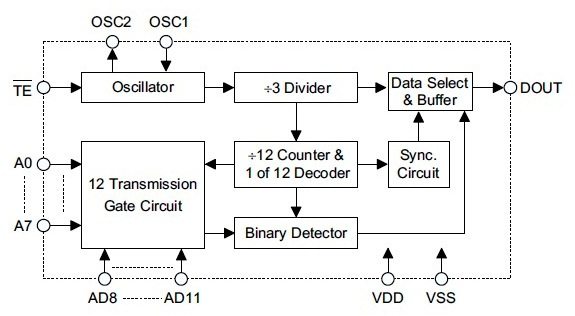
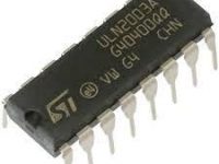
HT12E is able to operate in a wide voltage range from 2.4V to 12V and has a built in oscillator which requires only a small external resistor. Its power consumption is very low, standby current is 0.1μA at 5V VDD and has high immunity against noise. It is available in 18 pin DIP (Dual Inline Package) and 20 pin SOP (Small Outline Package) as given below.
Pin Diagram and Description
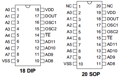
- VDD and VSS are power supply pins which are used to connect positive and negative of the power suppy respectively.
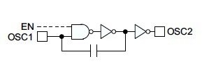
- OSC1 and OSC2 are used to connect external resistance for the internal oscillator. OSC1 is the oscillator input pin and OSC2 is the oscillator output pin.
- TE is used for enabling the transmission and is an active low input.
- A0 – A7 are the input address pins. By using these pins we can provide a security code for the data. These pins can be connected to VSS or left open.
- D8 – D11 are the input data pins. These pins can be connected to VSS or may left open for sending LOW and HIGH respectively.
- DOUT – It is the serial data output of the encoder and can be connected to a RF tranmistter.
Working
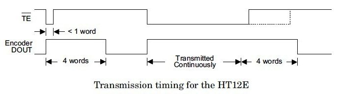
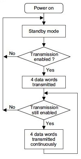
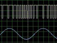
The HT12E 212 series encoder starts a 4 word transmission cycle upon receiving transmission enable signal on TE input. This output cycle will repeats as long as the transmission is enabled. When the transmission enable (TE) signal switches to HIGH, the encoder output completes the current cycle and stops as shown above. The encoder will be in the Standby mode when the transmission is disabled.
Typical Application Circuit
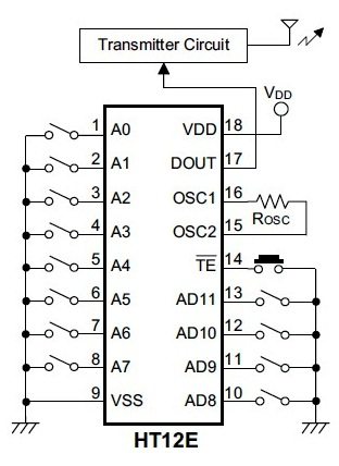
Use Rosc = 1.1MΩ as recommended in the datasheet.


750k
How to transmit data from different rf transmitter to singal rf receiver? If possible plzz help me out by mailing to [email protected]
HT12E and HT12D with IR ?
hey ..
I need help GUYS ..
I am using HT12E and HT12D for control home things with remote I have made circuit but I am not getting right frequency for IR transmitter….
use 1M resistor for HT12E and 47K/or 47K+3.3k resistors for HT 12D ., I am using this configuration and works well with RF modules.
And also, can it be used with an IR transmitter?
Even I am facing the same issue. How to calculate the value of the required resistance?
What will hapen if I connect vdd to data pin of ht12e
.and what is the difference btw vss and open
i m not understand the osc resistance value by data sheet ….plz help me………how we select he value for that to complete the synchronization with the ht12d
Open pin will read as HIGH (1)…
Refer the datasheet to find details about optimum osc resistance..
1.what data corresponds to an open circuit?,,i,e,when a data input pin is not grounded,what data value does it correspond to?
2.how to calculate the optimum osc resistance?does it depend on the transmitter frequency of the rf
module?