

Monostable Multivibrator using 555 Timer
Contents
Monostable Multivibrator is also known as One Short Multivibrator. As its name indicates it has one stable state and it switches to unstable state for a predetermined time period T when it is triggered. The time period T is determined by the RC time constant in the circuit. Monostable mode of 555 Timer is commonly used for generating Pulse Width Modulated (PWM) waves.
Circuit Diagram
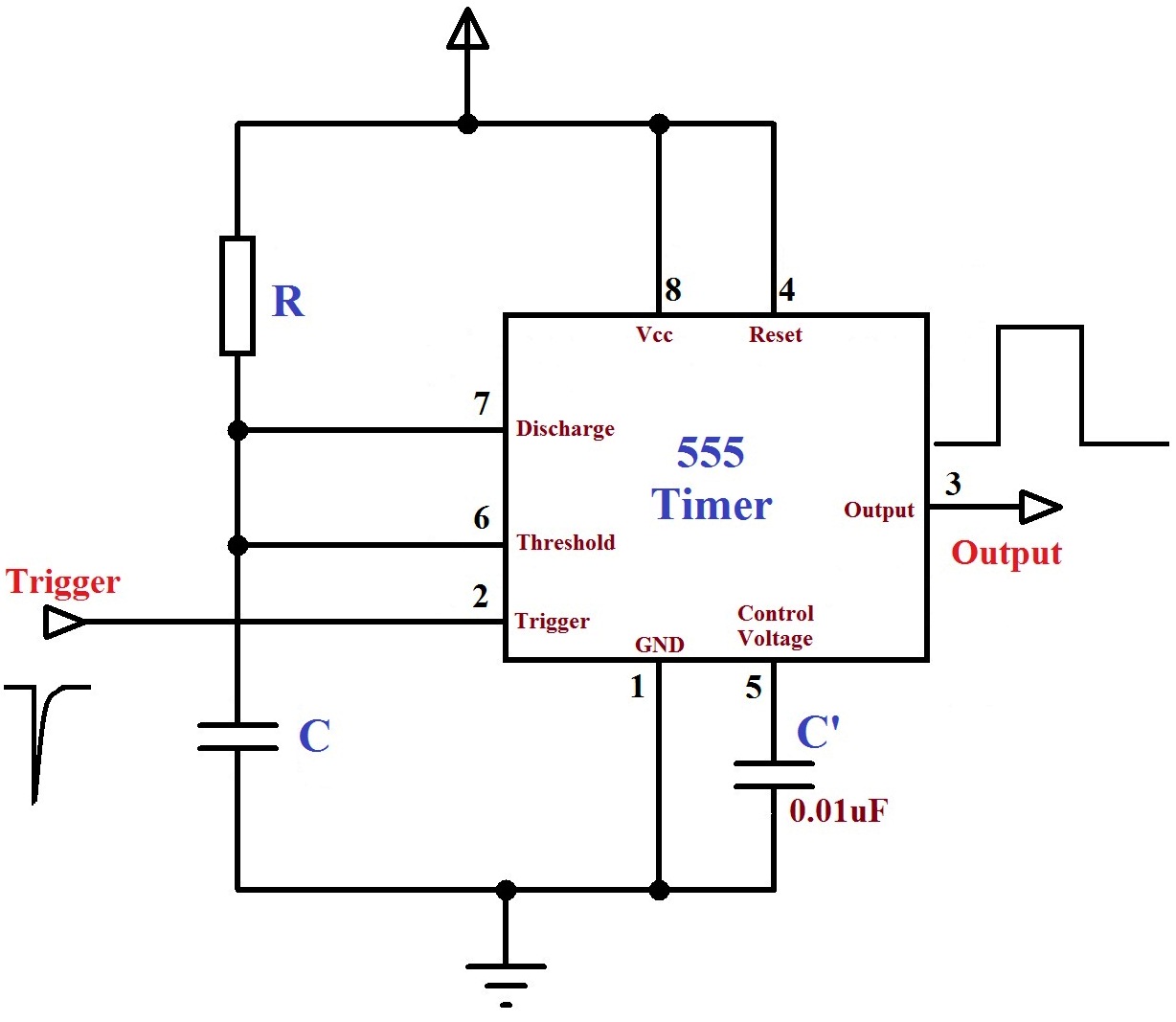
This is the circuit diagram of 555 Timer wired in Monostable mode. 8th pin and 1st pin of the 555 timer are used to given power Vcc and Ground respectively. 4th pin is the Reset pin of 555 Timer, which is active low so it is connected to Vcc to avoid accidental resets. 5th pin is the Control Voltage pin used to provide external reference voltage to internal comparators. Since it is not used here, it is grounded via a capacitor C’ (0.01µF) to avoid high frequency noises. When a negative trigger is applied on the Trigger input of 555, output goes high and capacitor starts charging through resistor R. When the capacitor voltage becomes greater than 2/3 Vcc, ouput goes low and capacitor starts discharging through the Discharge pin of 555 Timer. Time period of the unstable state is given the tye expression, T = 1.1RC.
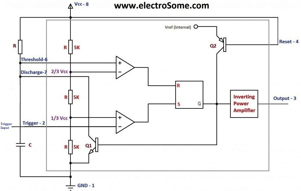
For the sake of explaining the working, circuit diagram with internal block diagram is shown below.
Circuit with Internal Block Diagram
Working
- The Monostable Multivibrator will be in its stable state (Output LOW) until it is triggered.
- When a negative trigger is applied to the Trigger pin of 555 Timer, output of lower comparator will become HIGH and output of upper comparator will be LOW, since the capacitor voltage is zero. This makes the output HIGH.
- The Discharge transistor turns OFF and the capacitor starts charges through resistor R to Vcc.
- After the negative trigger, output of lower comparator becomes LOW and that of upper comparator remains LOW. Since both inputs of the SR Flip Flop are LOW, output will not change, so the output is HIGH.
- When the capacitor voltage will become greater than 2/3 Vcc, output of upper comparator becomes HIGH and that of lower comparator remains LOW, so the output becomes LOW.
- This turns ON the discharge transistor and the capacitor discharges.
- The circuit remains in its stable state (Output LOW) until next trigger occurs.
Design
- Time Period, T = 1.1RC
Calculator


Very well described sir thanks a lot😊