

PIC to PIC Communication using UART
Contents
Introduction
PIC to PIC communication will be needed in some embedded applications. We have two options to transmit data through transmission lines.
- Parallel Transmission
- Serial Transmission
Parallel Transmission

In parallel communication an entire byte of data is transmitted at a time. That is each bit has dedicated line. Thus for 8-bit data transfer we need 8 dedicated lines as shown above.
Serial Transmission

In Serial Transmission only one bit of a byte is transmitted at a time. There is only one communication line, thorough which bits are transmitted sequentially.
Data can be transmitted using Parallel or Serial techniques, as the pros and cons of two methods are equal and the selection depends on application. Parallel Transmission is very fast compared to serial transmission, as it transmits a byte at a time. Serial Transmission is cost effective as compared to Parallel Transmission as it requires only one line for transmission.
Transmission Systems are also classified into 2 on the basis of transmission synchronization.
- Synchronous Transmission
- Asynchronous Transmission
Need for Synchronization
When an electronic device transmits data to other there must be certain synchronization between them, ie the receiving device must have a way to know the beginning and end of each unit (byte) of data.
Synchronous Transmission
Synchronous Transmission are synchronised using a clock line, ie the communications are time synchronised. An external clock line is also used along with data line to synchronize transmission and reception ends.
Asynchronous Transmission
There is no separate clock line in this system. Transmitter and Receiver works on separate clocks. Start and Stop bits are also send along with data to identify start and end of a byte.
We can transmit data in three ways.
- Simplex
- Half Duplex
- Full Duplex
Simplex

In Simplex Transmission, data is transmitted only in one direction.
Half Duplex

In Half Duplex Transmission, data can be transmitted in both directions but to one side at a time.
Full Duplex

In Full Duplex Transmission data can be transmitted simultaneously in two directions.
USART – Universal Synchronous Asynchronous Receiver Transmitter
USART is the most commonly used serial I/O module. It is also known as Serial Communications Interface (SCI). USART can be easily configured as a full-duplex asynchronous communication system that can communicate with peripheral devices, such as personal computers and CRT terminals, or it can be configured as a half-duplex synchronous communication system that can communicate with peripheral devices, such as serial EEPROMs, A/D or D/A integrated circuits, etc. USART can be configured in the following modes.
- Synchronous Master – Half Duplex
- Synchronous Slave – Half Duplex
- Asynchronous – Full Duplex
We don’t want to bother about configuring USART registers as MikroC Pro for PIC Microcontrollers have built-in library function to handle asynchronous communication.
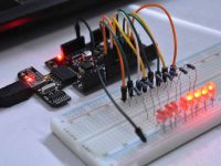
Circuit Diagram

The above circuit can demonstrate the PIC to PIC Communication using USART. Here we are using Asynchronous communication. The switch status read by the first PIC is transmitted to the second PIC and displayed using LED’s.
MikroC Code
Transmitter
void main()
{
  TRISB = 0xFF;
  PORTB = 0;
  UART1_Init(9600); // Initialize UART module at 9600bps
  Delay_ms(100); // Wait for UART module to stabilize
  while (1)
  { // Endless loop
    UART1_Write(PORTB); // and send data via UART
    Delay_ms(500);
  }
}
Receiver
void main()
{
  TRISB = 0;
  PORTB = 0;
  UART1_Init(9600); // Initialize UART module at 9600bps
  Delay_ms(100); // Wait for UART module to stabilize
  while (1)
  { // Endless loop
    if (UART1_Data_Ready())
    { // If data is received,
      PORTB = UART1_Read(); // read the received data,
    }
   }
}
Download Here
You can download MikroC files and Proteus files here..
PIC to PIC Communication using UART


Help me!!!
I cannot receive and send data at the same time. Do you have any solution?
MPLAB IDE natively doesn’t support these functions .You have to create them in your program.For info on how to create one refer book …..
Programming PIC Micro-controllers with XC8
By Armstrong Subero
Hello
I get this error: Error – could not find definition of symbol ‘UART1_Read’ in file ‘./project.o’.
Can someone help?
Hello Sir,
I am a beginner. I’m using MPLABX IDE 8.92.
I’m trying to write a code to interface gsm 800A with PIC16F877A. i wrote it and in the code i called uart1_write and uart1_init functions but the problem is i’m unable todefine these 2 functions.Please help me.
sir i also want that program kindly send me plz
You need to use two separate frequencies.
Otherwise you can use a duty cycle/frequency based transmission such that it won’t interfere each other.
If I have two RF receivers, how do i make sure that the data is received by only one of the receiver?
(without using HT12E/12D chips). Thanks
Sorry we don’t have any codes for that.
Kindly use our forums ( https://electrosome.com/forums/ ) for asking doubts outside the scope of above article.
please send me the code for sending and receiving characters for PIC to PIC serial communication.
hi this programme work but in industrie it is not securité to order motors i choud integret this informations in a trame ID binaire for example (1111) and in the end (00) and between then i make portb and i say for the pic recever iformations is (1111portb00) do portb in the metre pic =portb in the sclave pic (sorry im not good in english) i need ur help in programaation in mikroc
May be due to baud rate mismatch.
hello sir,
i am using 2 pic 18f45k22 controllers which communicate which each other in serial,asychronous full duplex mode.
One UC sends 3 bytes data on receiving which the 2nd UC should send 8 bytes of data to it in return, through serial tx and rx. I have compiled it (in mikroc) and works fine. when i simulate in proteus, the second controller’s 8 data bytes are visible in virtual terminal. but after connecting it to RX of 1st UC they are not appearing in VT. But I can see 8 bits transmitting in the line when i see through oscilloscope. I am not sure about what data is passing. I can’t understand where i have got wrong. Please tell me if i have missed something in the procedure.
It seems like you connected TX to TX and RX to RX INSTEAD OF TX to RX and vice versa.
Hello please i need some help with the tutorial “PIC TO PIC COMMUNICATION USART”
i’ve done it with pic 16F628A.
but proteus warning me : “logic contention(s) detected on net #0003”;
and the programm don’t work.
please help me to resolve my problem
Thanks.
hello please i’ve some problem with this tutorial.
i’ve realised it with the pic 16F628A. but i have some problem in my simulation on proteus.
Proteus warning me: ” logic contention(s) detected on net #0003″. and the programm simulation don’t work.
please help me
Sorry, I am unable to find the exact reason without sufficient information. Try changing ICs.
hi sir..my uart suddenly stop working..before this its works…i have check my crystal and transmitter and microcontroller all working good.but i cannot transmit or receive anything..pls help me sir..
Two while loop means ?
i have another question..how to use this receiver pic to detect metal..how to add two while loop in same program..help me pls..
Thabk you very much sir….Actually forgot to put delay after UART…..now its working… 🙂
For using ASK RF modules you should reduce the baud rate to lowest possible value. .. otherwise it won’t work..
Voltage in RC7 and RC6 may vary…. .you need a CRO for evaluating signals on those lines.
Above program is 100% working.. You should make GND of both devices common and make sure that RX is connected to TX of other device.
Sir need your help…im doing program for pic to pic communication using RF Module(RS433MHz)…i successfully wrote program and its works fine in proteus simulator….but its not works in breadboard….pls help me soon as possible i have only two weeks to submit my project
hi sir i wrote program in MikroC….no error and its works fine in proteus too….but when i test in breadboard no result…even no voltage at RC7(RX) and RC6(TX)…pls help soon as possible..i have only two weeks to submit my project..
Thanks for the feedback.
Many Many thanks sir for your Nice Explanation.
No, but you can develop it easily. .similar to above example.
do you have pic to pic communications using uart with lcd and keypad? thanks
Worked with me like charm 🙂 Thanks a million
Thanks for the feedback..
Hello, THANK you sir for this GREAT work, I have been looking for EXACTLY the same project with exactly code, thanks a lot for spending time teaching people good things.
Programming are done in mikroc pro..itself…
sir,can i use this for any microcontroller. sorry for my last question.
sir,can you help for this pic to pic communication done in mikro c pro.if any way to done this in mikroc pro? please help.
Make sure that your are using MikroC Pro..
If you are using mikroC pro.. then you shouldn’t include UART library..
goto View >>Library Manager … for that..
I posted the proteus files and mikroc fies as per your request.. you can download it from the end of this article..
sir ,i build this code with Mikro c Pro and it is not succesfully build,it show error:
undeclire UART1 error.What is the problem? please post yout proteus file and source code.
Yes……….the above tutorial is with two pic 16f877a.
Does this work with two PIC16F877A?
Sorry, I didn’t forgot…….. I have no time….. I don’t know the abcd of pic assembly language programming…. So it is a time consuming process for me….Please ask this question in edaboard , some assembly language experts may help you soon …
are you forgot about this project? :(((
how long does it takes to write code in mplab for you?
mplab/assembler 🙂 I cannot use MicroC, because I need this code only in these programming languages
Why don’t you use a high level language like MikroC……………??
Now most of the peoples are using high level languages.. for project developing.. as it don’t require more hardware knowledge and saves time….
Do you need complete assembly language code or Hi-Tech C code?
I will try……….. I am not yet used mplab….I am going to start learning it now…
can you put this code in few days? I really need this, please, this would be great 🙁
I would be grateful if you can do that in this week 🙂
I will update…it after some days…..Now I am busy……..
can you update your article with mplab and assembler codes? 🙂