

Solar Tracker system Using LM358
We all know that a Solar Panel can be used to convert light energy to electrical energy. The amount of converted energy depends on the amount of light falling on the Panel. Generally Solar Panels are stationary devices which is fixed at a position. The produced electrical energy can be increased if we move the solar panel as the movement of the Sun. Here is a simple low cost Solar Tracker circuit which automatically moves the solar panel in the direction of Sun. The movement of the Sun is detected using two LDRs which are arranged on the Solar Panel in such a way that the intensity of light falling on it varies as the direction of Sun changes.
Circuit Diagram
Working
The heart of the above circuit is two voltage comparators made using LM358 Dual Op-Amp. We all know that when the intensity of light falling on a LDR increases, its resistance decreases. Here LDR is connected with a series resistor (R3 & R4), hence when the intensity of light falling on a LDR increases, voltage across corresponding resistor (R3 or R4) increases.
The output of the voltage comparator will be high when the voltage at non-inverting terminal (+) is higher than the voltage at the inverting terminal (-). Inverting (-) terminals of both comparators are shorted and connected to a variable resistor (RV1), which is used to set the reference voltage. Thus the sensitivity of both LDRs can be adjusted by varying the 10K pot shown on the left side of the circuit diagram. When the light falls on a LDR increases, voltage at the non-inverting (+) terminal of corresponding comparator increases and its output goes HIGH.
The direction of motor rotation is controlled by the H-Bridge formed by the complimentary symmetry transistors BC547 and BC557. Consider the case when the output of first comparator (U1:A) is high and output of second comparator (U1:B) is low. In this case transistors Q1 and Q4 will turns on and the resulting current rotates the motor in clockwise direction. Consider the case when the output of the first comparator is low and the output of the second comparator is high. In this case transistors Q2 and Q3 will turns on and the resultant current rotates the motor in anticlockwise direction. If the output of both comparators are low, transistors Q3 and Q4 turns on, but no current will flow through the motor. Similarly if the output of both comparators are high, transistors Q1 and Q2 turns on, but no current will flow through the motor.
The DC Motor should be connected to the panel in such a way that, the rotation of motor rotates the panel in the direction of movement of the Sun.

Does this circuit work on 6v battery and 3v or 4v geared motor??
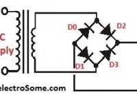
so why we using diodes in this circuit
Is it the motor can move clockwise and counterclockwise?
https://uploads.disquscdn.com/images/2e44f1bf8b087d7d6a9386a6f0f0af15282d5bdc688a5f02a11db2e2b539aadb.png
I dont get the power input. Is it 2 trrminal? Or 1 terminal? How can i make this work thank you
plz tell me what to do because your circuit is not running
Plz send me pic. Of this circuit diagram in to pcb
hello , i’ve just been realize it with old motor 7V and mecanical reducting from washmachine , it runs well , but the difficultie is getting back to sun in the morning , because it stops right eastwhen night appears , how to desequilibrate OP when morning light appear on west ? pulse with Ne555 ? or LDR impulse with Ua741 , ? thank’s for your opinion, (i’m french)
can u give me the block diagram of this project with explaination ? and project specification?
If the two LDRs are at the same intensity of light, resistance and hence voltage drop across them should be identical. If so, the output of the opamps seem to be either 0 or 1 for both opamps. Then the motor should not run. So please specify how to place the LDRs for proper functioning.
sorry. can you help me.i have problem. i need read with ADC_READ (pic18F4520)the tension above 380v but my resolution its 10 bit.. exemple
volt = (volt*40000)>>10; // input tension ref 0v and 5v
volt = adc_read(2);
volt = (volt*40000)>>10;
mil1 = volt/1000;
cen1 = (volt%1000)/100;
dez1 = (volt%100)/10;
uni1 = volt%10;
lcd_chr(2,9,mil1+48);
lcd_chr_cp (cen1+48);
lcd_chr_cp (‘.’);
lcd_chr_cp (dez1+48);
lcd_chr_cp (uni1+48);
lcd_chr_cp (‘V’);
Sir I need any preparing video can u provide any links
Sir can u send document to me or link of any preparing video
good evening,
may you modify the code of ultrasonic sensor sh-r04
to be 6 sensors and take the results to raspberry pi through spi.
also, if u donot mind give me ur email???
i am waiting your reply
thanks
faithful: john
sir, Is there any number for LDR………
Sir I constructed the circuit and it works well when I give leds but the motor is not rotating I have used the small.dc motor used in toys pls help with this
Sorry, we don’t have any report for this.
sir,
Can you please send me the report, components list for the DUAL AXIS SOLAR TRACKING SYSTEM to the mail—– [email protected]
I’ve building circuits for 45 years and I keep saying “This must be some kind of floating ground”! I had serious doubts about this ever working but Yes I built it anyway.
Turned the power on and SMOKE! Fried up all the components.Then i read the rest of your statements made in this post. “Do not have a prototype at the moment”
I went berserk-You kids get on here and post this to impress your boyfriends or girlfriends just to say “Hey look at me i;m on the internet!” Come to America and iI’ll stomp your ASS and get back my $5 for parts that you owe me for not even testing this in the real world.”F”ing Engineer . You couldn’t wipe my goats ass!
LM358 is very popular and commonly available.
Sorry, currently we don’t have any images of the prototype. Yes you can power it from 12V batteries.
HI, I WOULD LIKE A FULL COMPONENT LIST AND THEIR RESPECTIVE VALUE(INFO).
Hi Sir
Is it possible to use an alternative to the LM358?
Hi Sir,Good day,
Sir Is it possible if the source for the circuit system is using 12V batteries ?
If it is possible, how does it affects the circuit and Sir is there any images of these prototype built ?
THANK YOU SIR…
Yes, it won’t stop. You need to use some mechanical stoppers.
Hi sir the motor i got a problem . the motor doesn’t stop
No programming is required. It uses simple op amp ic.
does it require any programming?
Don’t you try changing the sensitivity ?
sir i made my tracker using the exact same specifications as you did, but the response or say the rotation of the motor is very less, almost negligible. How can i improve the response?
What will be the specifications of dc motor being used in above experiment.
hi. i have a question.
can you help me ?
Hello,
Please use our forums ( https://electrosome.com/forums ) for asking doubts not related to above topic.
sir i waiting plzzzzz as soon possible
hi respected sir ….
sir how i will interfacing digital light sensor(TSL45313CL) with 8051 micro controller to get value on 16×2 LCD….plz help …..
waiting for urs positive response …………
Try changing the resistance values.. 10K resistor and preset…
You should arrange LDRs properly… otherwise it won’t work..
Hi, you can use any NPN power transistor… eg: 2N3055
hi
the sensitivity of this tracker is very low!!!!!!!!!! so that it cant track the sun!!!!!!! can you tel me that how i can increase the sensitivity of system?
hi, i have 12v and 1amp gear motor to run a pack of panels can you tel me what kind of transistor or other elements should use in my project??????? can you give me some information using my email address?
thank you
youre sincerely
please give us the description of LDR used in the circuit, Sir !
I haven’t yet used TINA..
I am trying to simulate it before trying it but is not doing anything, I am using TINA. Have you use a simulator for this? If so, can you share the file? Thanks in advance
They are freewheeling diodes or flyback diodes..
They are intended to cancel the effect of back emf produced in the motor wingdings.. Just search and read about it..
Hello, 12V, 1W solar panel will not provide enough current for the working of motors..
How the diodes are useful in the above given circuit…..
thanks for thz i want to make the project ll you plz give me some detail on my email [email protected]
Hey don’t work!. I have everything like diagrams said
hey i made same circuit . brother it’s not working :/
dear Ligo George , could u suggest the suitable transistors at Q1,Q2,Q3,Q4 for the power rating 12v 5A
hello sir..i use a 12V 1W solar panel as the source 9-12V as the schematic diagram says. the motor doesn’t move even tough the ldr have been stimulated with bright light at one side. the output voltage gain are very small, in millivolt. can i know what is the prolem??
It might be the problem of the IC…
The output of the comparators will be +Vsat or -Vsat.. Which will be approximately equal to your Vcc..
thank U ^_^
I try it also it does not work !! , when shading LDR 1 i have 9 volt as output the VCC i used is 11 volt , when shading the other LDR2 i have onle 2 volt !! what would be the problem ? i tried to reconstruct the circuit for + 10 times , !! please HELP
Then you may use two reference 10K variable resistors.. for each comparators..
if the LDR1 and LDR2 has not equal resistance at the same level of lighting – which is the case i just face when i bought the circuit elements – also the 10k & 10k hasen’t the same value exactly (+ 4% or -4%) , does that affect ?? if yes , how could we solve this problem ?
It should be calculated depending upon the torque required….
You can change the driving transistors as per the current requirements..
what is the Power rating of motor you used? also can you suggest some motor for 1- 1.5 kg solar panel ? also what changes has to be made in the circuit according to the power of motor please. Thanks in advance 🙂
I think it will automatically turn back.. .according to the light falling on it..
Hi.can you tel me how i can turn back it to east next morning for solar panel uses?
ok thanks a lot.
Yes you can use mosfet………. base resistor is not required while using mosfet.. consider the current consumption of motos while choosing mosfet..
Ok thanks. Will mosfet do the job also?
Ya, sure… just replace 4 transistors depends on your current requirements..
Hi. Find this circuit while searching for a solar tracker on the net. Just assembled & tried it. Seems that the transistors burned out because the motor was drawing too much current. Can they be replaced by a higher amp transistor?