

Water Level Indicator and Controller using PIC Microcontroller
Contents
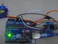
Here is a simple, versatile project which indicates the level of water and automatically controls it by using PIC Microcontroller. The Water Level Sensing Section senses the level of water in the tank and sends it (wireless) to the Receiver Section. Receiver Section is connected to the Controlling Section, which process the received information and produces visual, sound indications and controls the operation of the motor whenever required. The project is divide into 4 sections.
1. Power Supply Section
Power Supply section provides required supply for Receiver and Controlling modules. Receiver module requires +5V power supply. Controller module requires +5v and +12v supply. Circuit Diagram:

2.Water Level Sensing Section

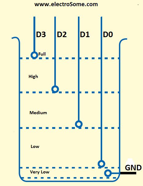
Level Sensor module is made of with HT12E encoder and ASK (Amplitude Shift Keying) RF transmitter. This circuit can be drive using 9V battery. For more details about this transmitter, please read the article Wireless RF Transmitter and Receiver using ASK RF Module. This circuit is placed near the Water Tank and connected to the tank as show in the figure below.
3. Receiver Section

Receiver Module is made of with HT12D decoder and ASK RF receiver. The data transmitted by the Sensor module is received by this module and is given to the Controlling Module. For more details about this receiver, please read the article Wireless RF Transmitter and Receiver using ASK RF Module.
4. Controlling Section
Circuit Diagram
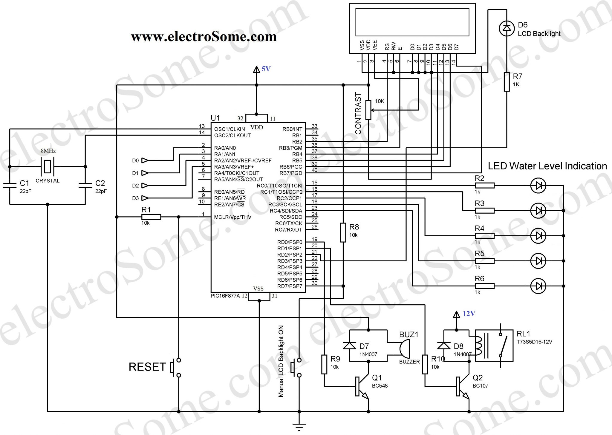
The soul of the Controlling Section is PIC16F877A. It process the data given by the Receiver Section. LCD Display, LED Indications and Motor status are updated according to the data. You can download the hex file and mikroC Source Code at the bottom of this article.
MikroC Code
// LCD module connections
sbit LCD_RS at RB2_bit;
sbit LCD_EN at RB3_bit;
sbit LCD_D4 at RB4_bit;
sbit LCD_D5 at RB5_bit;
sbit LCD_D6 at RB6_bit;
sbit LCD_D7 at RB7_bit;

sbit LCD_RS_Direction at TRISB2_bit;
sbit LCD_EN_Direction at TRISB3_bit;
sbit LCD_D4_Direction at TRISB4_bit;
sbit LCD_D5_Direction at TRISB5_bit;
sbit LCD_D6_Direction at TRISB6_bit;
sbit LCD_D7_Direction at TRISB7_bit;
// End LCD module connections

char txt1[] = "Water";
char txt2[] = "Level";
char txt3[] = "Indicator";
char txt4[] = "And Controller";

char mtr1[] = "Motor ";
char mtr2[] = "OFF";
char mtr3[] = "ON";

char wtr1[] = "Level: ";
char wtr2[] = "Very Low";
char wtr3[] = "Low";
char wtr4[] = "Medium";
char wtr5[] = "High";
char wtr6[] = "Full";

void main()
{

  int i = 0;
  int c = 16;
  int b = 0;
  CMCON = 0x07;
  ADCON1 = 0x06;
  TRISA = 0x0F;                  // set direction to be input
  PORTA = 0x00;
  PORTD = 0x00;
  PORTC = 0x00;
  TRISB = 0x00;                  //  set direction to be output
  TRISC = 0x00;                  // set direction to be output
  TRISD = 0x80;                  // set direction to be output

  PORTD.F2 = 1;
  PORTD.F7 = 1;

  Lcd_Init();                    // Initialize LCD
  Lcd_Cmd(_LCD_CLEAR);           // Clear display
  Lcd_Cmd(_LCD_CURSOR_OFF);      // Cursor off
  Lcd_Out(1,1,txt1);             // Write text in first row
  Lcd_Out(2,1,txt2);             // Write text in second row
  Delay_ms(500);
  Lcd_Cmd(_LCD_CLEAR);           // Clear display
  Lcd_Out(1,1,txt3);             // Write text in first row
  Lcd_Out(2,1,txt4);             // Write text in second row
  Delay_ms(500);

  // Moving text
  for(i=0; i<15; i++)
  {
    Lcd_Cmd(_LCD_SHIFT_RIGHT);
    Delay_ms(125);
  }

  i=0; //Motor Status OFF

  do
  {
    Lcd_Cmd(_LCD_CLEAR);
    Lcd_Out(1,1,wtr1);
    Lcd_Out(2,1,mtr1);
    if(c>0)
    {
      PORTD.F2 = 1               //LCD Backlight ON
      c--;
    }
    else
      PORTD.F2 = 0;              //LCD Backlight OFF

    if(b>0)
    {
      PORTD.F0 = 1;              //Buzzer ON
      Delay_ms(125);
      PORTD.F0 = 0;              //Buzzer OFF
      b--;
    }

    if(PORTD.F7 == 0)            //Manual Backlight ON
      c = 16;

    if(PORTA == 0x0F)
    {
       PORTD.F1 = 1;
       Lcd_Out(1,8,wtr2);
       Lcd_Out(2,7,mtr3);
       PORTC = 1;
       if(i == 0)
       {
          c = 16;                //Backlight
          b=3;                   //Buzzer
       }
       i=1;
    }
    else if(PORTA == 0x0E)
    {
       Lcd_Out(1,8,wtr3);
       if(i == 1)
          Lcd_Out(2,7,mtr3);
       else
          Lcd_Out(2,7,mtr2);
       PORTC = 3;                 //LED Bar
    }
    else if(PORTA == 0x0C)
    {
       Lcd_Out(1,8,wtr4);
       if(i == 1)
          Lcd_Out(2,7,mtr3);
       else
          Lcd_Out(2,7,mtr2);
       PORTC = 7;                  //LED Bar
    }
    else if(PORTA == 0x08)
    {
       Lcd_Out(1,8,wtr5);
       if(i == 1)
          Lcd_Out(2,7,mtr3);
       else
          Lcd_Out(2,7,mtr2);
          PORTC = 15;              //LED Bar
    }
    else if(PORTA == 0x00)
    {
       Lcd_Out(1,8,wtr6);
       Lcd_Out(2,7,mtr2);
       PORTD.F1 = 0;              // Motor OFF
       if(i == 1)
       {
         c = 16;                  //Backlight
         b = 3;                   //Buzzer
       }
       i=0;                       //Motor Status Updated
       PORTC = 31;                //LED Bar
    }
    else
       PORTA = 0x0F;
   Delay_ms(125);


  }while(1);                     // Endless loop
}
Working
For the transmission and reception of data we have used Holtek encoder-decoder pair of HT12E and HT12D. Both of them are CMOS ICs working voltage ranges from 2.4 to 12v. The oscillator resistances are chosen according to the datasheet. When water level raises, the data pins of the encoder will be grounded corresponding to the level of water, which will be transmitted to the Receiver via ASK RF module. The received data is decoded by the decoder HT12D. LED on the receiver indicates that it is receiving data. Then the data is given to the PIC for processing.
| D0 | D1 | D2 | D3 | Status |
|---|---|---|---|---|
| 0 | 0 | 0 | 0 | All data pins are grounded, indicates tank is Full. |
| 0 | 0 | 0 | 1 | Water level is below D3 and above D2, indicates High level. |
| 0 | 0 | 1 | 1 | Water level is below D2 and above D1, indicates Medium level. |
| 0 | 1 | 1 | 1 | Water level is below D1 and above D0, indicates Low level. |
| 1 | 1 | 1 | 1 | Water level is below D0, indicates Very Low level. |
When the water level becomes Very Low, the motor will turned ON, buzzer sounds and the LCD backlight will automatically turned ON for 5 seconds. After this, when the water level reaches Full level, the motor will automatically turned OFF, buzzer sounds and the LCD backlight will automatically turned ON for 5 seconds. During normal operation you can manually turn on LCD backlight by pressing the Push button switch. The LCD indicates the Level of water (‘Very Low’, ‘Low’, ‘Medium’, ‘High’,’Full’) and the status of the motor (‘ON’ or ‘OFF’). The LED bar will also indicate the level of water.
Download Here
You can download the hex file, mikroC source code, PCB Design, Layout, Proteus and Orcad files here.


Sorry, current we don’t have this project with ARM7.
Sir can you help with programming it with arm 7
Try adjusting the contrast of the LCD using the potentiometer.
Dear Sir,
I am trying to learn PIC programming from your site
and very impressed. I built your Water Level Controller circuit and LED/LCD interface
using Ctrl-C Ctrl-V works !
However, due to my ignorance of the Language I am not able to progress further.
Inspite of your busy schedule, can I request you to please guide me ?
My problem is, for the Water Level:
D0 D1 D2 Status
0 0 0 Motor OFF
0 0 1 Motor Off (Permissible Limit)
1 1 1 Motor ON (WaterLevel LOW)
The above Cycle Repeats till Power off.
How to program the above ?
I like to use ASK RF Rx Tx Modules with PIC16F628A or any other PIC
you recommend WITHOUT the HT12E and HT12D ICs.
Ca you please HELP?
Thank you very much in anticipation.
Imsa Naga.
Hi,
I made circuit successfully and it is working but LCD display not reading anything , Just back light On /Off happening . I used 16*2 Display unit , always display is blank,
Can you give the details to rectify this issue ?
Shaju
if you are using salty water then 5v is workable otherwise in normal water 9v is required for conductivity
Sir , I didnt get this. what does D0 , D1 , D2 means ? is it a kind of sensor ? hm
Dear sir, how can add more water levels and monitoring LED s?
Is there any option to use SEVEN SEGMENT LED instead of LCD?
And can I edit any modification in hex file?
and how can add the monitoring led ?
SIr, how can add level 5 ,6, and above up to 10?
Yes, you can change it. But why you need 18F4550 for a water level controller ? In my openion 16F877A is more than enough for it.
Water Level Indicator and program pic 16F876
hi sir, can i change the PIC16F7787A to PIC18F4550?
Sorry, I can’t help you much without explaining about your project.
You can use our forums ( https://electrosome.com/forums ) if your topic is outside the scope of above article.
You can mail me if you need premium support : [email protected]
i need an algorithm for water level indicator in dam
i need a algorithm to check water level in dam
Hi,
Can you please explain in detail ?
can i get the algorithm for water level indicator in dams
You can use a simple conductor with low corrosion.
It depends on the level you want to detect. Make sure that the circuit is above that level.
what type of sensor do you use?
sir, how high should this be if i were to install it from the ground for a flood warning purpose?
Yes, the same program will work without LCD also.
HC-SR04 working perfectly for me in the water tank
sir we are not using lcd display…suppose we load same program cn i get output or not
Sorry, it is very difficult for us to customize program for each and everyone. If you want something like that, please hire one of our engineers and pay for it. It will help us to live.
Hi,
I did this project successfully but i would like to add something more like ds1307 clock and display time on screen and motor should not on between 6pm to 9 pm plus suction water empty protection if you can make it for me please modify the circuits and codes
You need to learn MikroC programming for understanding it.
PIC Microcontroller MikroC Tutorials : https://electrosome.com/category/tutorials/pic-microcontroller/mikroc/
Thank you sir.
I am new to mikroC programming so i want to know how to understand the program given by you.
if you have any tutorial or handouts or if you can suggest me a website from where i can understand the program. please reply as soon as possible.
Motor is connected in series with the relay.
You can use floating sensors or use ac sensing method.
sir, i want to know where the motor is connected in the circuit?
When we take on the use of a metal contact, so he is very perishable. What do you suggest for him?
yes, it is ready to be loaded.
Hello I use MPLAB IDE and MPLAB ipe to compile and progammare the pic , I wanted to know if the hex file in the document is ready to be loaded in the pic ?
Sorry, I didn’t understand you question.
from where to get the floating switch.. have searched abt and confused which kind of floating switch shuold work better ?
Hi Sir
Could please tell me how to make ON and OFF any pin from Pic as 5min ON and 2hours OFF, when did the coding, level indicator stop working
5V will not provide any electric shocks.
You can connect switch to any of the remaining IO pin but you should add it in the program.
Sir wont anyone feel any electric shock when I dip the +5V into the water when Im using pump and at the same instant someone uses the water?
i need to ON and OFF, PORTD.F3 from pic for 5 min ON and OFF for 2hours. will it possible, if possible can you please provide the code.
Dear Ligo
i need to ON and OFF on pin from pic for 5 min ON and OFF for 2hours. will it possible, if possible can provide the code.
how to connect (which pin) pB switch for manul motor on/off,and need to edit code for that?
For encoding and decoding signals to a single line for transmission.
Yes ofcourse you can.
Hi, Can you tell me the purpose of using HT12E & HT12D?
Hello sir can I add a water temperature sensor?
It might not be a good option.
Can I use HC-SR04 Ultrasonic Sensor for this?
You can change it in MikroC Project Settings. Don’t forget to rebuild the project after changing.
What if i used 10Mhz crystal insted of 8MHz?
You mean oscillator resistors for HT12E and HT12D ?
You can use 51K MFR and 1M resistors.
Hello, can I use different value resistors for the oscilators than the ones in the diagram ?
Sorry, I don’t understand your question.
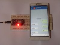
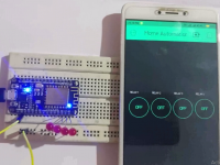
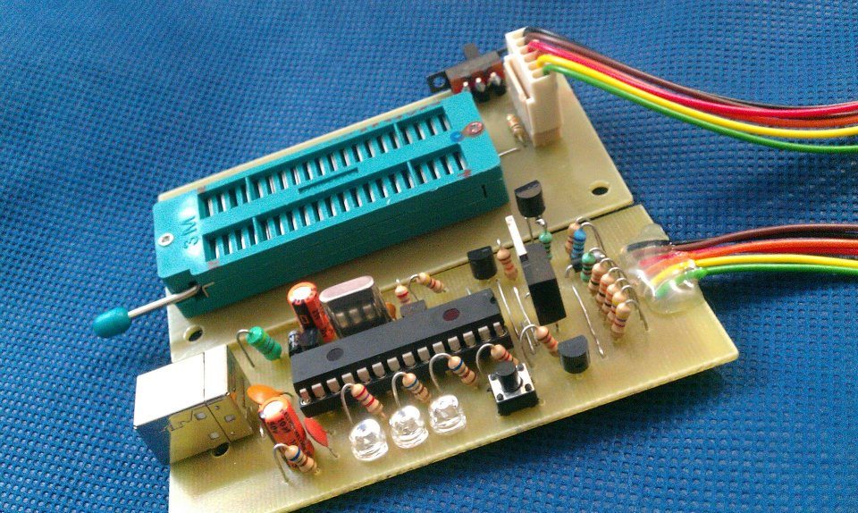
The above project is 100% working. You can see the completed photos of some users here.
Sorry, we don’t have any ppt.
thanks for providing code .At first time after simulation it is showing display in reverse no change in output
can you give any PPT of the project
my mail id is [email protected]
In HARDWARE or PROTEUS ?
The above project is 100% working.. you can see the comments below. Some of them posted the photos of finished items.
Lcd display is not showing any display and led is not glowing but code was sucessfully executed so where is the problem i can’t understand please help me.
All PCB files are available in the zipped folder.
Yes, you can;.. but you should do the programming of AT89s52..
pls give me the main circuit PCB DESIGN
Can i replace pic micro controller with 8051 or AT89s52 micro controller
connect it to.. ground and sensing pin in the transmitter.
If I wanted to use some float switches, that change from NO to NC or vice versa in place of bare wires, where would the two wires from these switches be connected? Thanks!
You may do it using wifi modules……
Is is possible to have the receiver unit hook up to wi-fi set up so the tank level information can be accessed on-line?
*.MAX files.. they are OrCAD files..
Hi George,
which file is related to pcb design and Layout.
Please let me know
Yes, you can do it.
Sorry, we don’t have code.
Can we do this project with AT89S52 Microcontroller???
Please dont mind, Iam beginner to embedded system.
If yes can you please send me the code on my mail. [email protected]
You needn’t replace any components. You can connect float switches directly.
Hello, your doubt is not related to above article, please use our forum for that :
https://electrosome.com/forums
Sir, what components should be replaced if I want to use float switches to detect the water level and without having to use Any ASK rf transmitter and amplifier? And would that be possible for the system to run?
pls chek the code sir…..i am sending uart data via UART terminal at mikroc. at virtual terminal of uart, data is coming correctly,but on lcd it is not diaplaying
sir, i want to display uart data(from gps module) on lcd 16*2… pls check the code in mikroc & 16f877a microcontroller
Yes, you may use 5 core cable with ground..
can i use with out wireless device? i want to use a 5 core cable?
http://electrosome.com/stepper-motor-pic-microcontroller/
Hi sir how can you write a code to run a stepper motor using micro c
Article updated…. try now..
Good day sir,
I have tried to understand your code one line by another but I found it difficult to do it because you don’t put comment next to you code for each lines.
I hope you can help me to understand you code better by putting more comments.
Kindly regards.
You may use floating switch..
Magnetic reed switch, tilt switch… etc..
It will be about 100 meter with proper antennas.
hey, by the way this have contacts in the water, which will corrode the elements and stop functioning later. there is another one without any connections with the liquid.
Any way good attempt. 4Sn.
pls tell me the maximum distance between transmitter & receiver
yess
are u tested it…sir…..???
You can use 433Mhz and 315MHz transmitter receiver pairs… as they are different frequencies they will not interfere.
sir, if we are using two set of rf module in same place they are not working. one rf reciever become off . they are getting interference from each other. how to remove it.
Here, it is not a big problem as the RF signals are already encoded and decoded……
If the problem still persists, it can be solved by proper programming..
Your project is nice but there is some problems in working time. RF communication is common through anywhere your device is caching all rf frequencies in surrounding….please try to modify that in usart communication…..
It will work without 22pF…
Hi sir, im doing this project now and i have a question. Is it only 22pFarad capacitor can be used in oscillator or we can use other value for it if not available. What will happen to the program if im not using a 22pFarad capacitor?
Yes,, but you need to program it.
It is given in the above circuit..
Note it from the above circuit diagrams
sir,can we use ARM(lpc2148) microcontroller in the place of PIC?
Hi sir, i have a project on water level with water pump. i dont know how to connect water in the tank to the motor with the pic16f887. thank you
Hello Sir ,can you list up the component that use in this project?
Use above project as reference..
Hi. Im doing a simple WIRELESS water tank project with pic18F4515 using mplab but i dont where to start i dont have schematic diagram can you help me with my project? my project needs only 2 LED (if the water its highest level the tank will automatically switch off) and we have to use float switch. please help me
can someone please list all the components /equipment for this project
Sorry, I don’t get what you are talking about.
block diagram
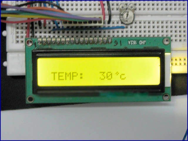
How are u Mr Ligo George I am doing the water level indicator project i attached the broke diagram but i am stuck with the circuit diagram now i found the almost similar project with mine bt this one include measuring water level and temperature i took the circuit diagram of it but now i want to remove the temperature component but i am falling to do it please help me remove the than i will be left only with the components of water level in the circuit here is the circut attached please u can even draw it on paper and scan it and upload it i want to simulate it using proteas software.
thank u sir Ligo
Sorry, I haven’t any circuit diagram,, check our adc tutorials.
can u plz provide me with a circuit diagram
No need to use Voltage to Frequency converter.. use Analog to Digital Converter.
Hlw mr Ligo George i am a student at Namibia i am currentry bisy with my project bt i am failing to come up with the circuit diagram can you please help me here is the scope of it its a water level indicator project
It mainly consist of following
blocks:
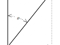
1. Potentiometer and pulley
arrangement: We have to measure the water level, for this purpose we are going
to use a pulley-float/potentiometer arrangement. Pulley will be hanged above
the water and a float will be resting on the water surface using a rope. And
potentiometer will be fixed at the center of the pulley. So as the water level
goes up and down, respectively pulley and potentiometer will rotate. So
eventually water level is converted into resistance of potentiometer. A
constant current source is used to pass current through this potentiometer, so
as to get a voltage drop. This voltage is given to amplifier.
2. Amplifier: As the voltage output
across the potentiometer is less, it has to be increased to 0 to 5 volts range.
We are going to use linear amplifier for this purpose.
3. Voltage to frequency converter:
The main part of our project is microcontroller (89s51) which reads only
digital input (0V & 5V) But the output of Amplifier is in analog form, so
it has to be converted into digital format, for this purpose we are going to
use Voltage to Frequency converter to convert analog output from amplifier into
the digital output to be given to microcontroller
4. Microcontroller: This is the CPU
(central processing unit) of our project. We are going to use 89s51, because it
belongs to the 8051 family. The various functions of microcontroller are like:
I. Reading the digital input from Volt to Freq converter which is derived from Potentiometer and pulley arrangement II. Sending this data to LCD so that the person operating this
project should read the values of Water level. III. Storing the data into
EEPROM memory and display it later using keypad IV. Sending the values of
temperature and light to the computer using serial port
.
6. LCD: We are going to use 16×2
alphanumeric Liquid Crystal Display (LCD) which means it can display alphabets
along with numbers on 2 lines each containing 16 characters.
Sorry, I haven’t the assembly code.
sir i want the complete assembly program so kindly give me the link
Yes, you can use 4MHz crystal.. Just edit the MikroC project settings and rebuild the project.
Hi, can I use a 4Mhz crystal instead of 8Mhz. If so, do I need to change and edit the source code. Please help me how to do it, because I’m new to c programming. Thank You
Download link is shown above :
http://electrosome.com/wp-content/uploads/2012/05/Waterlevel-indicator-controller.zip
hello sir ,where can ifind the source code .can you give the link?
You can remove that line CMCON = 0x07;
There is no CMCON register in PIC 16F877..
The above project is done using mikroC pro not using MPLAB IDE. You may use MPLAB for programming the hex file.
There is no problem with the program. It might be some hardware issues.
See the comments below, some of them successfully completed the above project.
I have edited the same code from above RAR, but its showing some errors (i have changed name only)
I have programmed the pic successfuly using mplab ipe but when im powering up it look like the controller is freezing and i have to reset many time before getting something in the screen and it freezes again
Build the code after editing, then the new hex file will be generated.
Then how to convert that file to hex
Download and install mikroC pro for pic microcontroller… open wli.mcppi using that..
You can find C code there and edit it. .
1) what file should i use from above RAR,…….
ASM or MicroC.
2) which lines i have to change
Please give me some instructions.
Yes, it is possible.. You can edit the source code..
While starting LCD display its showing “Project developed by———————–” . Is it possible to change that names in source code.
Use a simple aerial antenna.. or simple wire antenna.. without these turns..
I have used antenna by using Copper wire(shown in attached pic)
I think, it is the problem of your antenna… Try using simple wire antenna or Aerial antenna..
Hi, Its not sensing from tank(first floor) to main controller with receiver(in ground floor), if both are in same floor its working, so what should i do.
Hello,
Thanks for the feedback. 🙂
……….
I have done this project, its working successfully, thanks for this project
ok, i will try, thank you
Why did you use Manual Device Select ? PICkit 2 can automatically detect the target. .
Uncheck Programmer >> Manual Device Select
Try changing the PIC Microcontroller..
And the above project is done using PIC 16F877A.. not using PIC 16F877
hi, While programming to IC i am getting some problem (see in photo attached)
Hello,
Please elaborate your problem….. I don’t get it..
yes, just change the pic in mikroc project settings..
Hi, While programming to IC i am getting some problem, so please help me..
hi, can i use PIC 16F877
You don’t need ULN2803 for this project..
I need or not the ULN2803?
Which Country?
I use a uln2803 because is not available ask transmiter in my country,it doesn’t mather right?
Download the above zip file and extract it.
Hi sir, can i have the this source code in c language or assembler cause i cant see the hex file in the file i downloaded.
[email protected]
Try online shopping..
You can download the entire code at the bottom of above article.. just before the ads..
If haven’t yet done it with float..
hi Shri kamble do u have any idea abt water level indicator with float …if u know just mail me to [email protected]…thanks for advance..
It is not available ask transmitter receiver and decoder in my country.how can I get these.
i got the whole program of this, comment your id here 😀 😉
this is not a complete water level controller. sump tank sensor is missing
i have difficulties with programming of ic 16f877a. can i get programmed ic.
No…. Due to current passing in the wires.. Because of electrolysis the copper will be eaten Up with a time less than 1 week. ( I Faced the same problem) “sorry fro bad english”
i made this wlc on a breadboard and it works fine.The only problem i found was there is no dry run protection for the motor..
can i use this controller without RF transmitter? i prefer normal sensor probes eg: float switch, will it work ?
can I use PIC16F887A in this Project, if yes help in getting the source code
can I use PIC16F887 in this Project, if yes help in getting the source code
will copper wires be efficient as sensors in this project??????
there is no download option ….please help in getting the code..
There might have some connection problems.. above circuit and program is 100% working..
Hi Ligo, i couldnt get any thing on the LCD despite programming successfully with PICKIT2 using hex file you’ve provided.but the LEDS and buzzer are working in a continuous loop i dont understandwhat might be the reason there is nothing displayed on the LCD(rest everything including LCD backlight working,also I tried the contrast preset but nothing on the Lcd).please help.
Simply connect a push button switch to a IO pin of PIC.. make that pin input … see our pic tutorials..
VB Code??
This project hasn’t any interface with PC..
i need to add a manual switch to on the motor(When the water level is above medium or other case ). What changes i need to made to the code?
can u plz send me the vb code
[email protected]
Without RF antenna?? Every RF wireless device should have an antenna to radiate energy..
i need a circuit with out using rf antenna
what should i do
We can’t do proteus simultion.. since transmitter and receiver are not available in proteus library..
you may use multiple transmitter/receiver with different frequencies..
You need only one microcontroller.. .which is used in receiver module
how can use Proteus for simulation if the tanks are out of the site?
I would like to know also if i want to have multiple water tanks what should i do?
that is good,but do i need two microcontrollers for receiver module and transmitter module or just one? if it only one PIC how is it connected to receiver and transmitter module.
You can have about 100 meters range with proper antenna..
good day sir.. i would like to ask if how far will be the maximum distance of the rf transmitter to the receiver?.. thank you
ooppss..thank you sir…
There is a small mistake…….
RX of PIC should be connected to TX of UART Converter..
and..
TX of PIC should be connected to RX of UART Converter..
Hope you got it..
sir.. i edit the circuit diagram so i can interface it to the pc and visual basic.. is this correct..thanks
Of course .. it will work…
oh i get it now.. i will put it on RA0- RA3.. thanks sir.. i have 1more question sir.. if i wil put uart converter or max232 and rs232 to connect it to serial port of the computer and display it through visual basic instead of the LCD.. will it be working?.. thank you
See the labels on data pins on pic and rf receiver (HT12D)…..
good day.. i have a question.. where or in what pin im gonna connect the rf receiver to the pic16f877a.. sorry kinda new to this one..
Yes you may use….
. IR –> Infrared
RF —> Radio frequency..
IR allows only Line Of Sight communication and less range.. RF has no such problems..
can we use ir transmitter insteed of rf transmitter?>What’s difference between both?
Here is mikroc project settings.
Dear Friend What is the Configuration of PIC16F877A
I don’t get what you said..
Yes, it does glow. Here is another problem, why everytime it read data from RX, it always reset? Sometime, when controller read HIGH to MEDIUM, then the controller reset again, not live feed.
Does the LED in the receiver circuit glows when the transmitter circuit is turned ON?
That LED indicates that the receiver circuit is receiving data from transmitter….
You might have burned the encoder or/and decoder by misplacing them..
OK, but seem, the output is not really good, where in case LOW level is detected, but, all output at HT 12D is HIGH. so how?
HT12E – Encoder – (Data In) Reads data from water tank and gives it serially to RF Transmitter……..
HT12D – Decoder- RF Receiver Receives data transmitted by Transmitter and it is given (serial data) to HT12E- it decodes it in to parallel output (Data Out)
George, one more thing, the RX will read input from each respective pins and give data to correspondence pins on decoder right? Eg: pin 10 on encoder take data from tank, and the data will be transmitted and give that data at pin 10 on decoder. Am I correct? If I’m correct, than my project actually faced problem with this thing, where, if one pin of DATA IN on encoder take reading from the tank, then, the all DATA OUT on decoder give HIGH. Hope you can help me. I did troubleshooting many times including changing ICs, TX and RX, osc value etc.
Don’t you see the above download link. You must login to download it.. Please register and login, its free..
how to dowload the code.
Actually, I don’t get your question… All binary numbers are represented using HIGH and LOW (here it is 5V and 0V)…
hi George, I want to ask, the output on decoder circuit is on what type? HI LOW or in binary number?
Yes … ofcourse…. change the clock frequency to 20MHz in the project settings and Build it again…
can i use 20 MHz crystal ??
This might be differs only in pin diagram.. I think so.. You can buy RF modules that I used from many online stores.. just search it…
Please tell me whether, can i use this RF transmitter and receiver with the above circuit? ASK RF transmitter and receiver are not available in my area.
kindly reply soon.
You might not have connected VDD and VSS of PIC microcontroller which is not show in the circuit diagram.. Actually VDD and VSS are hidden in proteus.. anyway I will modify the above circuit diagram by including VDD and VSS..
The above circuit is the actual one.. VDD and VSS of the pic microcontroller is not shown in that circuit diagram.. VDD should be connected to 5V and VSS should be connected to ground..
By the way do u hav an actual circuit for me to see the connections?
My proteus is working but led didn’t light up and hardware for led n LCD also didn’t light up
Yes, that 5V power supply is enough…. You should add enough filtering capacitors to avoid ripples as shown in the power supply circuit diagram..
i see. another thing, seeing the 5V as primary power supply for the controller circuit, is it sufficient to power up all the components eg PIC, level LED, LCD screen. FYI, i tried to make the PIC used the stand-alone power supply which is 5V, but not working. If i connected it to one source only, it lit up but somehow the display fluctuated. keep resetting.
12V is used to operate the relay that used to control the motor… If you wish to use 5V relay, then you can avoid 12V.. I think 5V relays for handling high currents are not available..
Hi Ligo. Long time no see. For your information, I already build up the circuit. Left things is to program the circuit into PIC. I just want to know, the 12V power source is necessary or not? because I dont see 12 V power supply connected to circuit that you created for simulation.
There is an option to download the complete project files… above…
sir can you please provide me with the complete code for the project.. its little urgent, as ma presentation is this weekend 🙁
In this system has one of particular water level unlike site having system.System design to maintain that particular water level.The tank contain inlet and outlet in order to insert water into tank and eliminate water from tank.Inlet and outlet should be activate when water level goes below and above of that particular water level separately.I wish to deploy this into paddy field.Since there require predefined water level for each mtime period.Your system having discrete water level is not practical when implement to paddy field.That’s why i selected float switch.I want to know about mikroc program of control section and how it change when apply float into this system..Look forward your reply…Thanks Ligo
You need to use an ADC….. Since wireless communication via RF module is required… only discrete values are possible.. from 0000 to 1111… total 16 discrete values possible… If you need more accuracy it will become more complex…
Hey Ligo,I wish to implement water level controller based on 16F877A PIC microcontroller. Important thing that detect the water level continuously using vertical float switch sensor.It gives output as resistance.I would like to know how float switch sensor apply to this system and how mikroc program for relevant change…Looking forward to your reply ASAP..thanks friend…
Yes, of course..
You may use 8051
But PIC is also cheaper, PIC16F877A costs below 3$..
hi can we use a cheaper or smaller mcu ? and how to modify the program
8MHz
wat is the crystal value???
Remove the relay and its driving circuits……….
LCD indications include motor on off status……. you can remove this by editing the program…
hey, what changes will be required if motor work is excluded i want only indication in lcd
You can write the hex file to the pic microcontroller in the downloaded zip file using a pic programmer…….if you want to convert the program to mplab……. take the logic of mikroc and write your own code……..
my circuit is already operation, but my problem now. i don know how to convert the programming to mplab because we study using the mplab..i dont have the converter and programer to install the programming in pic using mikroc… can u xplain more detail step to convert the programming to me.. or if u have the programming in mplab.. can email me [email protected].. tq
You can download the entire project files from the above download link…..
plz send the main board pcb layout to my email id
[email protected]
-thank you
That is a MikroC program written for PIC 16F877A microcontroller…….
It is a variable resistor use 10K, used to adjust the contrast of LCD……. You can use micro switches ,,,
what is the ‘contast 100’ in the circuit….?
and what type of switches that we have to use in place of ‘reset’ and’manual lcd backlight’?
Hi. I don’t get the code, sorry, I’m new to vb. I’m working to understand but it’s so hard. When I try to assemble your wli.asm file you provided, it has 400errors. And I don’t know what lines causes the errors.
And may I know please if what is its processor used?
like the sample code below:
processor 16f84
#include
__config _RC_OSC & _WDT_OFF & _PWRTE_ON
STATUS equ 03h ;define address for the status register
TRISA equ 85h ;define address for the tristate register for port A
PORTA equ 05h ;define address of port A
TRISB equ 86h ;define address for the tristate register for port B
PORTB equ 06h ;define address of port B
ORG 0x000
BSF STATUS,5 ;switch to bank1
MOVLW B’00000000′ ;set port B as output port
MOVWF TRISB
MOVLW B’11111′ ;set port A as input port
MOVW TRISA
BCF STATUS,5 ;switch back to bank0
start
MOVLW 01h
MOVWF PORTB
GOTO start
END
Pardon to have so much questions. Just want to understand it, hope you helps ♥ thanks.
Yes you can download codes etc from above link……..
Hi, would like to ask if do you have a code for this ? I want to try this in virtual breadboard. We have a finals for PIC Microcontroller, and I’m searching for easier but working one 🙂 Looking forward to your reply. Thanks and Godbless.
Take the logic from mikroc and convert it to mplab..
You need a PIC Programmer for writing program to pic..
HOW CAN I BURN THE PROGRAM TO IC….?
How i can change the programming using mplab??
yes I meant the transmitter and receiver. I want to use the two for wireless sensor monitoring connected to the Arduino uno. Thanks for the response
You mean transmitter & receiver? ……. Encoder and Decoder IC contains Address pins A0 – A7…… in both transmitter and receiver, status of these address pin should be same……
how do you pair the two or there is no need to pair the two they will automatically pair?
Yes, of course……
Thanks. I will post it to you when its working. Btw, I’m looking forward to work with you with other project. Maybe we can work together.
Yes it is working perfectly ….. You can buy the rf transmitter & receiver online from extereme electronics or robokits…
ok. thank you. btw, this project is really working right? in term of rx and tx circuit.
If it is ASK TX and RX you can connect HT12D and HT12E to its appropriate pins
hi. I feel curious about the tx and rx circuit. I found one RX and TX module, but the leg is not same. If i use that, still can work or not?
No, it is dangerous……………..
Hi, could this project be modified to read diesel tank level instead of water?
Variable C is used to light led backlight when switch is pressed or when motor on off conditions occur………b is used to sound the buzzer 3 times……….
i can’t understand the program clearly. please add comment with each instruction..and send a copy to my email address: [email protected]
It may be the decoder or encoder IC probelm………check with another IC …….also check for unwanted shots………..
I don’t understand the last sentence you said….
I understand ……..bt the receiver of decoder D1 is always shown +5 volt it doesnt generate 0 volt is it the decoder IC problem??????????? I gave implement input…..D0,D1,D2,D3 (Close)……by the reverse condition D3, D2,D1,D0 (Open) Isnt correct loop????????
There are only 5 valid conditions for D0, D1, D2, D3
as shown in the table given in the article………Please refer it……….Un-implemented inputs may generate un-predictable outputs……….
I face a new prob……when I D0 throw ground Level: Low , Motor ON. but when D1 is grounded Its showed Level: Very Low,Motor On. after that D2,D3 grounded Level:” “, Motor:” “……….All the connection are correct and ok…………but when I remove D1 from receiver of decoder Its work proper but D0 is showed both level: Low/Medium.and finally D2,D3 was showed correct data…… now what should i do…..plz help me..The LED in the receiving circuit is glowing………..
Check the transmitting and receiving circuit……….The LED in the receiving circuit will glow when it receives signals from the transmitting circuit……..
I completed this project in bread board , connect the all component correct connection but Transmitting or Receiving system does not work properly. Hang up always indicate Level: Full, Motor OFF. How could i solve this problem? plz help me……….
programming is done using mikroc pro…….
the circuit can be simulated using Proteus and PCB designing is done using Orcad 9.1 whose files are included in the zip file…
what others software that i need to used in this project,except for the microC pro software??because i found that i can’t open some sourcecode in the Zip file..
I have included the source code along with the zip file…………
ok.tqvm..
Do you mean programmer or compiler?
The programming is done by using MikroC Compiler….
You can download the trial version from their site : http://www.mikroe.com/mikroc/pic/
Trial version is sufficient for this….
Yes…can we get that programmer languange? thank you..
You can get if from a good electronics shop……..
Do you mean the programmer to write program to PIC Microcontroller?
where can I buy the materials needed for this project?
can we get the programming of this project??
You may use 4 or 8 MHz……
dear friend pls tell me the crystal value
More than 100m……..
Dear friend how much distnce it will work