

IR Transmitter and Receiver using 555 Timer and TSOP1738
IR Transmitter and Receiver pair can be easily made using 555 Timer, IR LED and TSOP1738 IR Receiver. This can be used for remote controls, burglar alarms etc. TSOP1738 is a very commonly used IR receiver for PCM remote control systems. It has only 3 pins, Vcc, GND and Output. It can be powered using a 5V power supply and its active low output can be directly connected to a microcontroller or microprocessor. It has high immunity against ambient light and other electrical disturbances. It is able to transfer data up to 2400 bits per second. The PCM carrier frequency of TSOP1738 is 38KHz, so we want to design a astable multivibrator of 38KHz. This can be done by using 555 Timer.
Transmitter
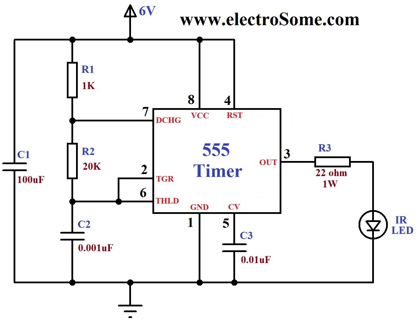
In the above circuit, 555 Timer is wired as an Astable Multivibrator. The 100μF capacitor (C1) is used to reduce ripples in the power supply. 1st and 8th pins of 555 are used to give power Vcc and GND respectively. 4th pin is the reset pin which is active low input, hence it is connected to Vcc. 5th pin is the Control Voltage pin which is not used in this application, hence it is grounded via a capacitor to avoid high frequency noises through that pin. Capacitor C2, Resistors R1, R2 determines the time period of oscillation. Capacitor C2 charges to Vcc via resistors R1 and R2. It discharges through Resistor R2 and 7th pin of 555. The voltage across capacitor C2 is connected to the internal comparators via 2nd and 6th pins of 555. Output is taken from the 3ed pin of the IC. Please read the article Astable Multivibrator using 555 Timer for more detailed working. Charging time constant of the capacitor (output HIGH period) is determined by the expression 0.693(R1+R2)C2 and discharging time constant (output LOW period) is determined by 0.693R2C2. They are approximately equal.
You can use the RESET pin of 555 for transmitting binary data.
Note : Output frequency of above circuit is about 35.2KHz. As per our experiment TSOP1738 is detecting it but you will get more range if you use exact 38KHz. You may also use 18K resistor instead of 20K which will produce 39KHz. Better you can try a preset for accurate 38KHz.
Receiver
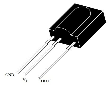
For receiving signals send by the transmitter you need only TSOP1738. Connect 5V to Vs and Ground to GND pin of TSOP1738. The output will be active low. Output of TSOP1738 will be HIGH when no signals fall on it and the output will be LOW when 38KHz infrared rays fall on it.


Thank you sir. I tried it, but when IR sensor is blocked and motor starts running, it just run for 2-3 seconds and stops (even though IR is falling on receiver). Is there any solution for this?
You can use a Transistor as a Switch.
How to get active high output? I mean when, 38kHz fall on the Receiver, it should start the motor. Otherwise motor should be in off condition.
Encoding is required only if you want to control more than one devices or for transmitting any data. Here 38KHz is enough.
But in your circuit you have not used any kind of encoding. Then how the circuit is working?
For that probably you should use a microcontroller. With above circuit we can only do ON OFF controls.
Can you make wireless servo controller using 555 ic
Thanks for your prompt response. Much appreciated!
I recommend you to refer the datasheet of TSOP1838. It is written ,”The data format should not make a continuous signal transmission. There must be a Signal Gap Time(longer than 15ms) at least each 90ms.”. So I think this behavior is expected for TSOP1838.
Hi i am using tsop 1838 and grounded a LED to output pin. On bringing in range of IR transmitter using [email protected] blinks once and cone back to ideal (High) stage… but in presence of remote LED keeps off till remote switch is pressed. Does transmitter require any sort of modulation?
Above project is for one channel only.
Where’s the receiver circuit? If I want to control, say 3 channels or 3 devices?
You can use C1 = 1nf, R1 = 1.6K and R2 =18k…the frequency will be approximately 38khz.. Thats very close
good morning sir
need help in IR based circuit
Can we use R1=7.5KHz&R2=7.5KHz so the frequency would be 38.4KHz
1. Make the transmitter frequency near to 38KHz
2. Increase the power of transmitter.
3. Use some reflectors and concentrate IR to the receiver.
Sorry, I don’t understand your question. The above circuit is doing the same thing. The IR led will glow at a frequency near to 38KHz. You can use a camera to check whether the LED is working or not.
howto increase or decrease the ir receiving range in ir receiver using tsop 1738 as i do not get any other receivers
Hello
i need some help. i would like the infrared led to blink.
any ideas guys?
thank you
You can reduce the transmitter power. Increase the value of series resistor of IR LED.
You can tune the 555 oscillator to exact 38KHz, it will give you more range.
Yes, you are right. But it will still work. Anyway I updated a note on the article regarding this.
Thank you.
Guys, your ranges are actually very small. If your transmitters are properly tuned at 38KHz, you should be able to get easily 5-8 meters, under proper conditions. If your transmitter frequency is off by more than 5%, then it needs to be addressed, otherwise you’ll be shooting in the dark trying to figure out what’s going on.
Please i want to interface Ir sensor like Tsop1738 with 8051 microcontroller, Can you help me in writing a code for it in C language……..
I want circuit with minimum range 1 meter….
only 18 cm
any longer circuits
GOOD STAFF